Table of Contents
- Introduction
- Included Cables and Modules
- Powering
- Options for Integration
- Connecting to RedEdge
- Triggering
- GPS Data
- Downwelling Light Sensor (DLS)
- Storing Data
- Aircraft
- Mission Planning
- Processing Data
Introduction
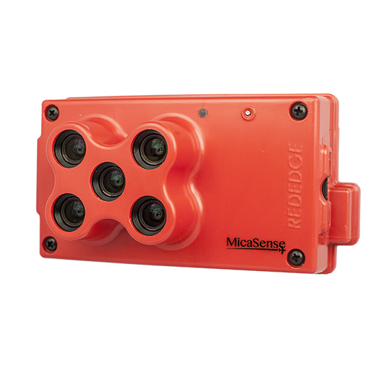
RedEdge provides multiple options for integration - from stand-alone (where you only provide power to the camera) to fully integrated. Advanced integrations take advantage of flexible interfaces including Ethernet, serial, RTK, and PWM/GPIO trigger, for seamless integration with any drone.
The default configuration for RedEdge uses the provided cables and modules - see RedEdge QuickStart Guide for more details. You can also explore the various options for integration below and choose the best fit for your configuration.
Included Cables and Modules
- 3DR GPS module
- Downwelling Light Sensor (DLS)
- 3-pin cable for power and optional external trigger
- 6-pin cable for connection of camera to either DLS or GPS module
- 6-pin cable for connection between DLS and GPS module
- 4-pin cable for connection between the DLS and GPS module (for mag sensors)
Powering
RedEdge requires 5.0 Volts DC for operation, with a maximum operating voltage of 5.5 Volts. The supply must be able to provide 10W (2A@5V) peak. Power can be provided to RedEdge in 3 main ways:
- a 5.0-Volt battery pack
- a rechargeable Lithium-Ion battery pack with appropriate BEC or power supply
- shared power from aircraft's main battery pack (with BEC or power supply if needed).
For more details, see How do I power the RedEdge?
Options for Integration
There are four basic ways to setup RedEdge. The following summaries will help you choose the one that meets your needs. Once you have determined the basic components of your setup, continue to follow this guide for triggering, mounting, and other considerations.
A) Default

The default configuration integrates the included GPS module and the DLS. To see the default configuration using the provided cables and modules, please see the RedEdge QuickStart Guide. Then continue to follow this guide for triggering, mounting, and other considerations.
B) Serial/Ethernet data & DLS
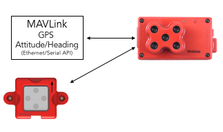
If you will not be using the provided GPS module, please ensure that your autopilot / payload computer sends both GPS data (latitude/longitude/altitude and date/time) and attitude data (pitch angle, roll angle, heading angle) using either the serial interface (MAVLink protocol) or Ethernet interface (custom API) - see the RedEdge API for details.
Continue to triggering, mounting, and other considerations.
C) Default GPS (no DLS)

The DLS is not required in order to use RedEdge. Whether flying with or without the DLS, always capture calibrated reflectance panel images before and after each flight.
Continue to triggering, mounting, and other considerations.
D) Serial/Ethernet data only (no DLS)

If you will not be using the provided GPS module, please ensure that your autopilot sends both GPS data (latitude/longitude/altitude and date/time) and attitude data (pitch angle, roll angle, heading angle) using either the serial interface (MAVLink protocol) or Ethernet interface (custom API) - see the RedEdge API for details.
Whether flying with or without the DLS, always capture calibrated reflectance panel images before and after each flight.
Continue to triggering, mounting, and other considerations.
General Considerations
Connecting to RedEdge
To make changes to RedEdge settings, you can connect to the RedEdge web interface using WiFi or Ethernet. For more details, see How do I connect to RedEdge?
Triggering
RedEdge supports three methods for capturing images: Timer mode, Overlap mode (recommended), and External Trigger mode (optional). You can configure these settings in the RedEdge WiFi Configuration > Settings page.
The optional External Trigger mode enables commanding a capture from the autopilot or payload computer using either a Rising Edge, Falling Edge, short PWM, or long PWM.
For more details, see RedEdge: Automatic Triggering Options
GPS Data
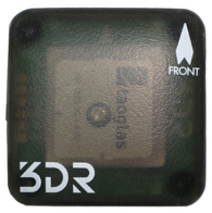
In order for RedEdge to properly geotag images and self-trigger, GPS data must be available to the camera. The simplest way to get started is to use the included module. Alternatively, you can send GPS data using MAVLink (Serial) or HTTP API (Ethernet) - refer to the RedEdge API.
For more details, see RedEdge: GPS Options
Downwelling Light Sensor (DLS)
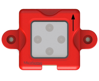
The Downwelling Light Sensor (DLS) is a 5-band incident light sensor that connects directly to a MicaSense RedEdge camera. The DLS measures the ambient light during a flight for each of the five bands of the camera and records this information in the metadata of the TIFF images captured by the camera. This information can then be used by specialized processing tools (like Pix4Dmapper) to correct for global lighting changes in the middle of a flight, such as those that can happen due to clouds covering the sun.
The sensor should be mounted on a mast with a clear view of the sky, and completely unobstructed so that no part of the aircraft can cast a shadow on the light sensor.
The DLS is not required in order to use RedEdge. Whether flying with or without the DLS, always capture calibrated reflectance panel images before and after each flight.
For more details on the connections and mounting considerations, please see the DLS Integration Guide
Storing Data
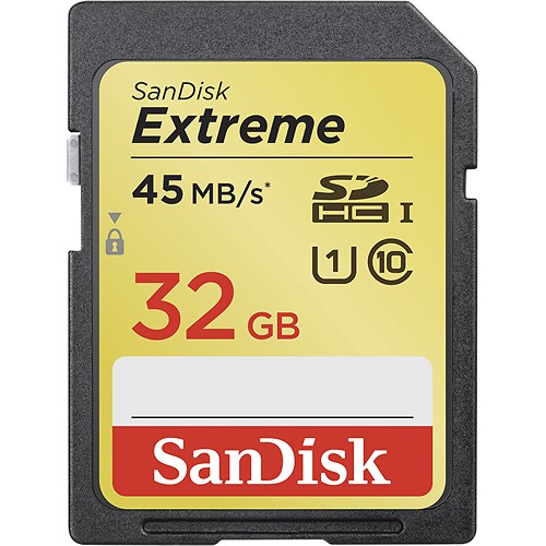
RedEdge comes included with a 32GB SDHC class 10 card. It is only compatible with FAT32 formatted SD cards. For more details, see SD Cards for RedEdge.
Aircraft
The RedEdge is well suited for both manned and unmanned aircraft of all kinds.
Camera Specifications
Please see the detailed specifications outlined in the RedEdge Integration Guide to guide your integration.
Multicopter Mounting Considerations
When mounting a RedEdge on a multicopter, we highly recommend using a gimbal to keep vibration to a minimum and to ensure that the camera is pointing straight down (nadir).
Since the RedEdge features global shutters which will be less affected by normal vibration, a fixed mount is also a reasonable option. With a fixed mount, be sure to angle the camera to compensate for the pitch of the aircraft as it flies. The goal is to keep the camera pointing straight down (nadir).
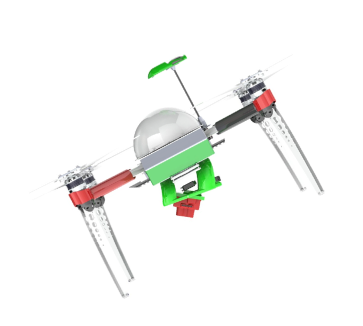
The DLS and GPS should be mounted on TOP of the aircraft such that the DLS is pointing straight up, with a clear view of the sky. The DLS should not be shadowed by any objects, including the propellers. For this reason, it is best to place the DLS well above the aircraft, on a mast, if possible. If using the GPS module (which in addition to GPS data also provides magnetometer data), this module must be placed on a mast to avoid electromagnetic interference that will affect its magnetometer readings.
For more details, see "Mounting Considerations" in the DLS Integration Guide
Fixed-Wing Mounting Considerations
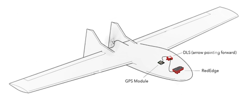
It is important to ensure airflow around the camera for cooling.
Normally, the camera should be in landscape orientation. If you plan to mount the camera in a portrait orientation, remember to swap the vertical and horizontal parameters in your mission planner.
Ensure that the camera is protected during landing. We do not recommend using a lens cover, but if you use lens protection, make sure that the lens protection you use does not filter the various wavelengths captured by the camera.
If using the GPS module (which in addition to GPS data also provides magnetometer data), this module must be located such as avoid electromagnetic interference that will affect its magnetometer readings.
For more details, see "Mounting Considerations" in the DLS Integration Guide
Mission Planning
Software
There are many desktop and mobile applications available for planning your mission. Your software will need information about RedEdge (like the field of view) in order to generate an appropriate flight plan. Please see this article for important RedEdge parameters to input into your software. MicaSense offers a free iOS application for DJI drones which automatically works with the RedEdge. See Atlas Flight for more details. If using a third-party flight planner, ensure that it supports the camera parameters or you will not collect data with the expected overlap.
Best Practices
How you capture data is critical to produce high quality output. Our best practices guide takes you through everything you need to know.
Best practices: Collecting Data with MicaSense RedEdge and Parrot Sequoia
Processing & Analysis
Data captured with RedEdge conforms to standard formats (TIFF) with standard metadata that can be read by a number of image viewer and processing applications. Since five separate TIFF files are created for each capture and they are not registered/aligned with each other, photogrammetry software is required to align/register the bands and create a georeferenced orthomosaic from the data. After creating the orthomosaic or reflectance map, you can calculate agricultural indices and create color composites to help analyse the data.
Processing
Data captured with RedEdge can be processed with a variety of photogrammetry applications, including solutions by AgiSoft, Icaros, and Pix4D. When processing with Pix4Dmapper, there is a "Send to Atlas" button you can use to send the processed data to MicaSense Atlas for analysis. For more details on how to process RedEdge data in Pix4D, please see this article.
For users and partners that would like to implement their own raw image processing workflow software, we have published a series of tutorials and software on the use of RedEdge imagery and metadata for achieving the best results. You can find the tutorials and code in github here: MicaSense Image Processing.
Analysis
Atlas is a simple to use cloud based platform built to provide intelligent solutions for precision agriculture. After processing raw data with Pix4Dag or Pix4Dmapper, turn imagery into actionable information using powerful analytics and visualization tools. Backed by the cloud, this dynamic platform allows for easy sharing and mobile access.
Processed RedEdge data can also be analyzed in a variety of applications, including open-source applications like QGIS, which can generate NDVI and other agricultural indices and color composites.