MicaSense RedEdge-MX™ and DLS 2
Integration Guide
Revision 04
November 2020

Seattle, WA
Introduction
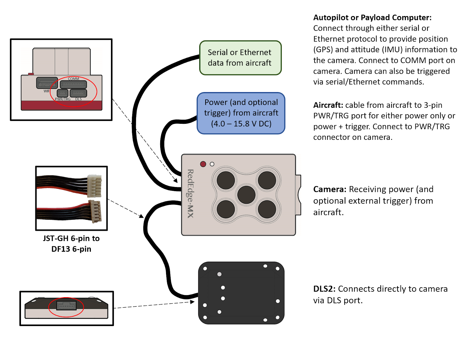
MicaSense RedEdge-MX provides multiple options for integration - from stand-alone (where you only provide power to the sensor) to fully customized integrations. Advanced integrations take advantage of flexible interfaces including Ethernet, serial, and PWM/GPIO trigger, for seamless integration with any aircraft.
Firmware
It is important to have the latest version of firmware installed on your sensor. Please see the following page to get the latest version and learn how to update your firmware: https://www.micasense.com/firmware-updates
What’s Included?
For the most current list of what's included, see our RedEdge-MX packing list article
Lens and Imager Information
| Multispectral | |
| Pixel size | 3.75 μm |
| Resolution | 1280 x 960 (1.2 MP x 5 imagers) |
| Aspect ratio | 4 : 3 |
| Sensor size | 4.8 mm x 3.6 mm |
| Focal length | 5.4 mm |
| Field of view | 47.2 degrees horizontal, 35.4 degrees vertical |
| Output bit depth | 12-bit |
| GSD @ 120 m (~400 ft) | 8 cm/pixel per band |
| GSD @ 60 m (~200 ft) | 4 cm/pixel per band |
Center wavelengths and bandwidth
Cameras with serial number RX02 or higher
| Name | Center | Bandwidth |
| Blue | 475 nm | 32 nm |
| Green | 560 nm | 27 nm |
| Red | 668 nm | 16 nm |
| Red edge | 717 nm | 12 nm |
| Near infrared | 842 nm | 57 nm |
Cameras with serial number RX01
| Name | Center | Bandwidth |
| Blue | 475 nm | 20 nm |
| Green | 560 nm | 20 nm |
| Red | 668 nm | 10 nm |
| Red edge | 717 nm | 10 nm |
| Near infrared | 840 nm | 40 nm |
Imager/band number and output
| 1 | Blue |
| 2 | Green |
| 3 | Red |
| 4 | NIR |
| 5 | Red edge |
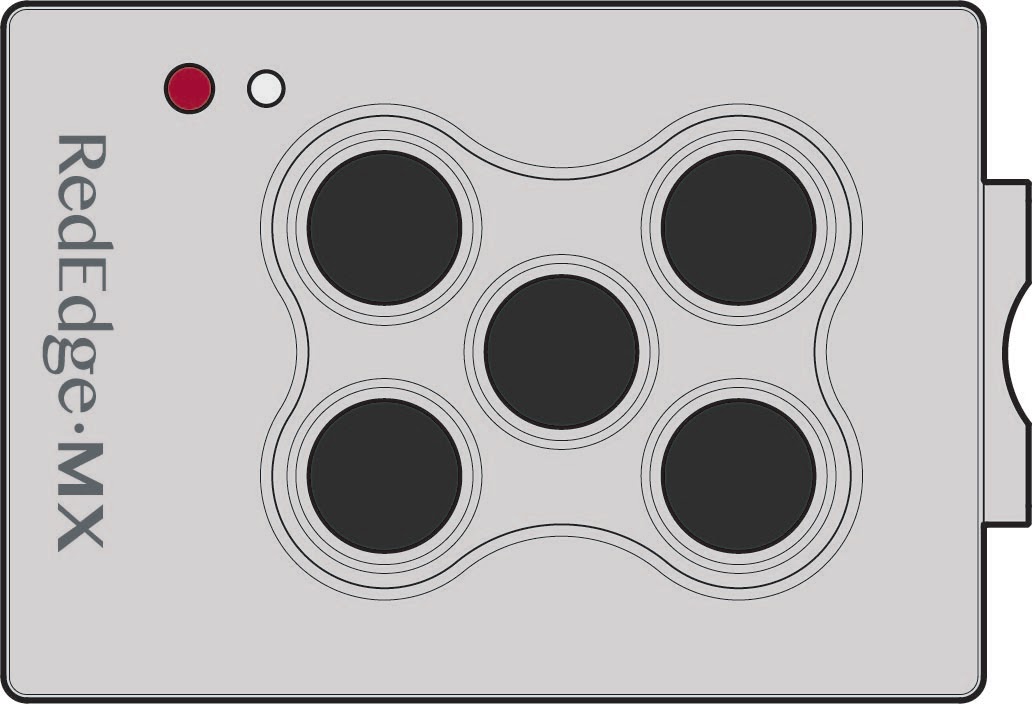
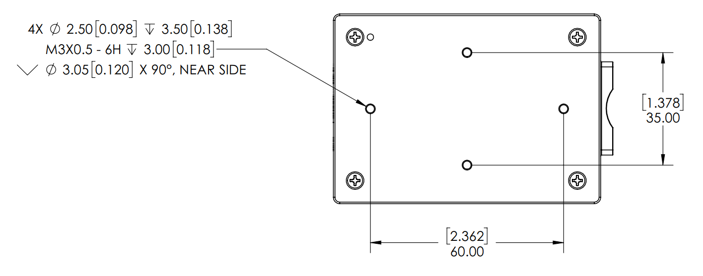
Measurements and Attachment Points
There are four M3 screw holes at 60 mm x 35 mm on-center. The sensor can be attached to the host aircraft using at least two of the four provided threaded mounting points and M3 x 0.5 screws. If using only two mounting points, it is important to choose two threaded points opposite of each other.
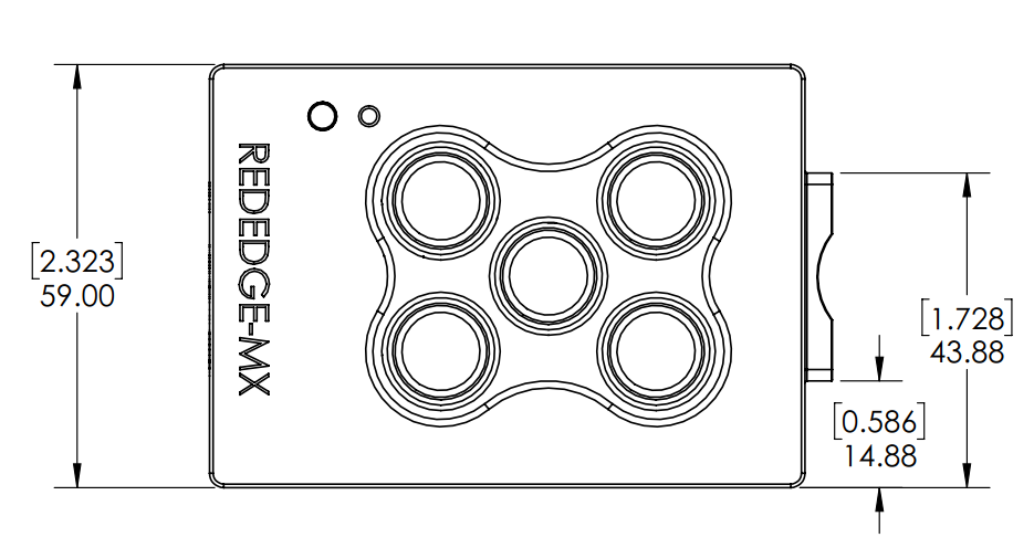
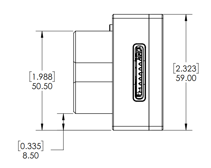
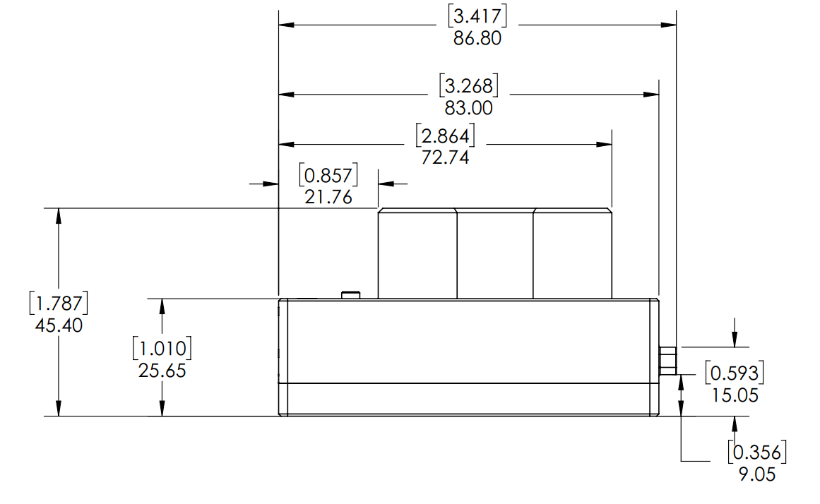
| Length | 83 mm |
| Width | 59 mm |
| Height | 45.4 mm |
| Mass | 231.9 g (Camera + DLS 2) |
Recommendations for Installation
The RedEdge-MX should be installed such that it has a clear view of the area directly below the aircraft. The “cone” of the lenses, which has the widest field of view (47.2 degrees horizontal, 35.4 degrees vertical), should be considered in the process of deciding where to mount the sensor on the aircraft or payload bay.
The multispectral sensors feature a global shutter and can withstand some vibration without degrading image quality; nevertheless, we recommend vibration isolation between the sensor mounting platform and the aircraft.
Make sure the sensor points straight down (with respect to the earth) at all times during flight. The best way to ensure this is to use a gimbal.
Normally, the sensor should be in landscape orientation. If you plan to mount the sensor in a portrait orientation, remember to swap the vertical and horizontal parameters in your mission planner.
Ensure that the sensor is completely protected during landing. Note that we do not recommend using a lens cover during flight as it can filter the wavelengths that the sensor measures. Instead, protect the sensor with a recessed installation or by using landing gear.
Use the provided lens cover when storing your camera, and do not set the RedEdge-MX lens-side-down as it will rest on and scratch the lenses.
More integration guidelines for the DLS 2 are in the DLS 2 section of this guide.
Configuration Options
There are many ways to configure the RedEdge-MX. The following summaries will help you choose the one that meets your needs. Many other options are possible. If you have any questions about your integration, please contact support@micasense.com
Default + Overlap mode
The default configuration uses the DLS 2’s integrated GPS. Use the provided cable to connect the DLS 2 to the camera. Ensure the DLS 2’s physical installation meets the requirements outlined later in the DLS 2 section of this guide. Connect a compatible power supply to the camera’s power pins. For more details about power, see the Input and Output section of this guide.
Once attached to the aircraft, use the Flight Calculator to determine the necessary overlap percentage for your desired Ground Sample Distance and Target Altitude, then input the parameters into the Overlap settings, outlined in the Triggering section in this guide. The sensor will begin capturing once it is within the Target Altitude Tolerance of your Target Altitude. It will capture often enough to maintain your overlap percentage at your desired altitude. This will ensure enough coverage to create a mosaic of your flight area with your preferred photogrammetry software.
Default + trigger by HTTP API
With this configuration, instead of automatically capturing with an automatic triggering mode, the HTTP API (see below) is used with an onboard computer to trigger the camera at intervals determined by your computer. See examples of the HTTP API here: Integration examples for MicaSense sensors.
MAVLink with PixHawk or similar flight controller
The RedEdge-MX can be triggered with a PixHawk flight control system using the serial API. MicaSense cameras currently use the MAVLink v1.0 messaging protocol for the serial API, which the camera uses to interact with PixHawk. You can read more detailed information here: Guide for MicaSense Sensors and PixHawk.
DLS 2 with Aircraft GPS
For more control, advanced users can communicate with RedEdge-MX by HTTP (Ethernet, Wi-Fi) or serial (MAVLink) using the MicaSense APIs (Application Programming Interfaces). The APIs can be used in lieu of the DLS 2 GPS to provide the sensor with a position and attitude data (from the aircraft GPS, for example). Anytime GPS data is sent to the sensor via the API commands, it will be written to the image metadata, overriding the DLS 2 internal GPS data for five seconds (or until another update is sent via the API).
HTTP Connection
Attach a USB Ethernet adapter or USB Wi-Fi adapter to one of the USB 3 ports. See the User Guide for MicaSense Sensors for connection details and information. For HTTP API details, visit https://www.micasense.com/api
Serial Connection
Use the provided ethernet cable to connect to your serial device. See the Input and Output section of this document for pin layout and details. Visit https://www.micasense.com/api to learn more about communicating with the MAVLink API.
Input and Output
The RedEdge-MX & DLS 2 sensor kit includes all necessary cables for integration. If extending the cables, ensure that the voltage at the camera is at acceptable levels as outlined in the “Powering” section of this guide.
The RedEdge-MX camera features 3 connectors for interface to peripherals and to the host aircraft. A fourth connector (USB Type A) is used for the Wi-Fi module (included).

External Power and External Trigger (“PWR/TRG”)
| Pin # | Signal |
| 1 | Trigger |
| 2 | Ground |
| 3 | Power |
| Connector on Camera | Hirose DF13A-3P-1.25H(51) |
| Mating Connector | Hirose DF13-3S-1.25C 28AWG wire recommended |
Pin 1 indicator (Δ) on DF13 family of connectors (DF13-3S-1.25C shown)
Power Input
| Item | Value |
| Nominal Voltage | 5.0 V DC |
| Input Voltage Range | 4.0V-15.8V DC |
| Average Power | 3.5 Watts average, 8.0 W peak (Camera Not Providing Power to External GPS Module) |
| 4.0 Watts average, 8.5 W peak (Camera Providing Power to External GPS Module) |
-
The average power requirement of the RedEdge-MX integrated with a DLS 2 is 4.0W. However, the camera can require instantaneous power of up to 8.0W during operation for brief periods of time. Ensure the power supply can reliably source 8.0W during operation while remaining within the operating voltage range. Operation outside of the specified input voltage range may result in unreliable operation or damage to the camera.
-
The RedEdge-MX contains under-voltage and over-voltage protection circuitry which nominally applies at 3.8V and 16.0V. However, over the operating temperature range these cutoff voltages can vary by up to 0.2V. For reliable operation, ensure the supply voltage remains within the operating input voltage range at all times over the full range of operating conditions.
-
Trigger input: The camera can be triggered either with a rising-edge pulse, falling edge pulse or a PWM signal (such as is typically used with standard servos). When using a PWM signal as the trigger, the camera detects a transition from a “long” PWM to a “short” PWM (or vice-versa depending on the configuration setup of the camera)
| Item | Value |
| Nominal Voltage | 3.0 V DC |
| Voltage Range | 0.0 V DC to 5.0 V DC |
| Absolute Maximum Voltage | 5.1 V DC |
| PWM Trigger Expected Range | 1.0 ms to 2.0 ms |
| CAUTION |
| Care should be taken when multiple “grounds” are used for power and trigger of the camera. Only one ground should be connected to the camera – typically this is the ground that corresponds to the source of the power. If the ground of the trigger signal and the ground of the power source are different, they should not be joined together electrically at the camera. Contact support@micasense.com if further information is needed. |
| Pin # | Signal | Direction |
| 1 | 5.0 V DC Output | Output From Camera |
| 2 | DLS 2/GPS RX | Output From Camera |
| 3 | DLS 2/GPS TX | Input To Camera |
| 4 | GPS IO 0 (Configurable) | Input To Camera/Output from Camera |
| 5 | GPS IO 1 (Configurable) | Input To Camera/Output from Camera |
| 6 | Ground | Ground |
| Connector on Camera | Hirose DF13A-6P-1.25H(51) | |
| Mating Connector | Hirose DF13-6S-1.25C28AWG wire recommended | |
Serial and Ethernet Data (“COMM”): This connector is available for tighter integration with host aircraft. It includes a standard TTL-level serial port as well as an Ethernet port. Documentation for the communications protocol is available by contacting MicaSense.
| Pin # | Signal | Direction |
| 1 | Serial RX (3.3 V) | Output From Camera |
| 2 | Serial TX (3.3 V) | Input To Camera |
| 3 | Serial Ground | Ground |
| 4 | Ethernet RX P (B+) | Output From Camera |
| 5 | Ethernet RX N (B-) | Output From Camera |
| 6 | Ethernet Line Ground | Ground |
| 7 | Ethernet TX P (A+) | Input To Camera |
| 8 | Ethernet TX N (A-) | Input To Camera |
| 9 | Ethernet RX P 1G (D+) | Output From Camera |
| 10 | Ethernet RX N 1G (D-) | Output From Camera |
| 11 | Ethernet TX P 1G (C+) | Input To Camera |
| 12 | Ethernet TX N 1G (C-) | Input To Camera |
| Connector on Camera | Hirose DF13A-12P-1.25H(51) | |
| Mating Connector | Hirose DF13-12S-1.25C28AWG wire recommended | |
Power supply specifications
| Voltage | 4 V - 15.8 V |
| Standby | 5.5 W |
| Average | 3.5 Watts average, 8.0 W peak (Camera Not Providing Power to External GPS Module) 4.0 Watts average, 8.5 W peak (Camera Providing Power to External GPS Module) |
RedEdge-MX requires 5 V DC for operation, with a maximum operating voltage of 15.8 V. The supply must be able to provide 10 W peak. Power can be provided to the sensor in two main ways:
- shared power from aircraft's main battery pack
- a rechargeable Lithium-Ion battery pack (a two-cell LiPo will provide optimal efficiency).
Ensure the power source conforms to the specifications listed above and can supply the required voltage at the power port of the camera, accounting for any losses in the wiring.
USB port
The RedEdge-MX features a USB port which supports the following Edimax wifi adapters:
- EW-7611ULB (requires RedEdge-MX firmware version 7.0.0 or higher)
- EW-7811Un (V2 of this model is not supported)
Capture Rate
The RedEdge-MX capture rate is heavily dependent on the storage device. The RedEdge-MX kit includes a 128 GB SD card which has a maximum capture rate of about 1 second per capture. When setting up a mission or flight plan, adjust the desired overlap, flight altitude, and speed so that the capture interval does not exceed the maximum capture rate.
For details on how the sensor writes files to the storage device, see the File Storage section of the Sensor User Guide.
Automatic Capture/Triggering
RedEdge-MX supports three methods for capturing images: Overlap, Timer, and External Trigger. To learn more about how to configure these settings, please see the User Guide for MicaSense Sensors.
Overlap (recommended)
In Overlap mode, when the aircraft climbs to within your chosen Target Altitude Tolerance below your Target Altitude, RedEdge-MX will start capturing and only take a capture if it has traveled forward enough distance to ensure the overlap percentage you have specified. Prior to RedEdge-MX firmware release 7.1.0, the Target Altitude Tolerance was fixed at 50 meters, but this can now be specified by the user. When the sensor's altitude is below the Target Altitude Tolerance from the Target Altitude, the sensor stops capturing. Overlap mode only calculates the forward overlap, and cannot account for the side overlap, which must be calculated in a flight planner, using the sensor’s field of view to create an appropriate row spacing.
We recommend this mode because it helps ensure proper overlap (75% or higher), which is essential in order to produce high-quality output when processing the data in standard photogrammetry software.
Timer
When in timer mode, RedEdge-MX will capture according to the timer period, which is every two seconds by default. If the timer period is set to capture faster than the storage device can write the captures, inconsistent capture intervals may result. The capture rate is heavily dependent on the write speed of the attached storage device, and is prone to unreliable physical capture spacing if the aircraft does not travel at a constant ground speed. See the USB Storage and Ethernet and Capture Rate headings in this guide for more details.
External Triggering
For more control, you can enable external trigger mode to talk to RedEdge-MX by PWM or edge triggering. This document contains detailed pin information.
External Trigger
The sensor can be set to trigger by the rising-edge of a pulse, the falling-edge of a pulse, or a PWM signal (such as is typically used with standard servos). When using a PWM signal as the trigger, the sensor detects a transition from a “long” PWM to a “short” PWM (or vice-versa). When using PWM, rising-edge, or falling-edge, ensure that the input signal’s ground is connected to the isolated ground pin on the camera.
HTTP API (Ethernet and Wi-Fi)
The HTTP API is the most powerful way to interface with the RedEdge-MX. You can use this API using either the Ethernet connector or the camera’s Wi-Fi access point.
The API is accessed via HTTP connection to port 80 at the sensor IP address. Most data is exchanged in the JSON format.
The actual value of the IP address depends on the configuration. When accessing the sensor via its Wi-Fi access point, the sensor IP address will be 192.168.10.254. When the sensor is connected to an Ethernet network, the sensor IP address will be 192.168.1.83 by default.
The sensor can be commanded to take a capture by either a GET or POST request to the /capture URL.
For more information, please see https://www.micasense.com/api
For examples, please see these articles:
Serial API
The Serial API provides a MAVLink interface to the RedEdge-MX. You can use this API by connecting your MAVLink-capable system to the host serial port on the sensor.
The API is accessed via serial messages in the MAVLink format. MAVLink provides an open data format for interaction as well as a suite of tools to assist the programmer in developing and testing the interface. RedEdge-MX uses MAVLink v1.0 messages and communicates with the host at 57600 baud.
For more information and examples, please see https://www.micasense.com/api
Disabled
“Disabled” should be set when triggering via Skyport (PSDK), HTTP API, or the serial (MAVLink) API. This mode disables the camera’s automatic triggering functions, and will require trigger commands directly from the drone via PSDK, HTTP, or MAVLink, depending on the integration.
Downwelling Light Sensor 2 (DLS 2)
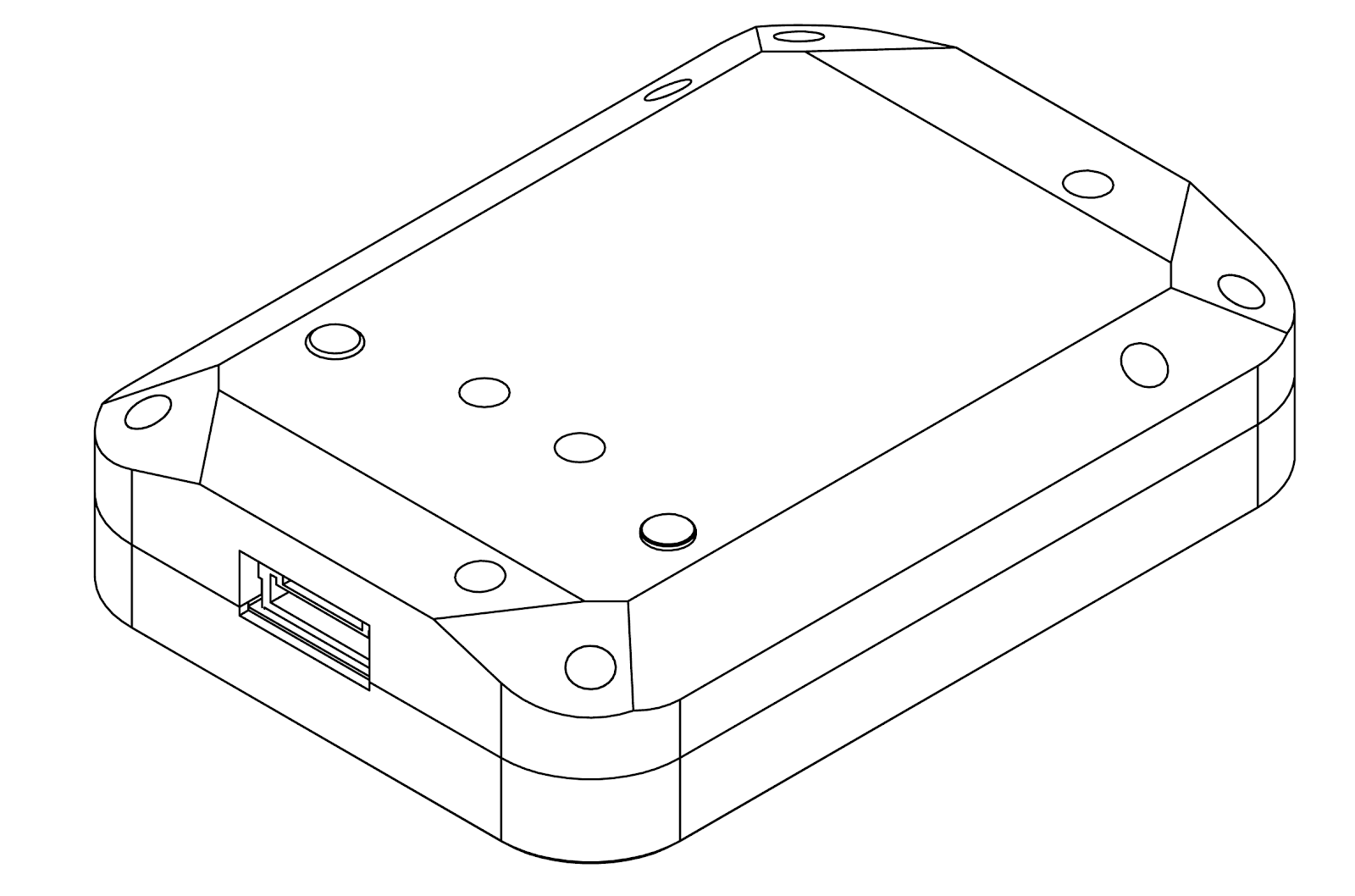
The Downwelling Light Sensor (DLS 2) is an advanced incident light sensor that connects directly to RedEdge-MX. During a mission, the DLS 2 measures the ambient light and sun angle and records this information in the metadata of the TIFF images captured by the camera. This information can then be used by specialized processing tools (like Pix4Dmapper) to correct for global lighting changes in the middle of a flight, such as those that can happen due to clouds covering the sun.
In addition, the DLS 2 provides GPS data to RedEdge-MX unless GPS data is provided from an external source as outlined earlier in this guide. If using an alternative GPS source, the GPS receiver will remain on at low power.
Measurements and Attachment Points
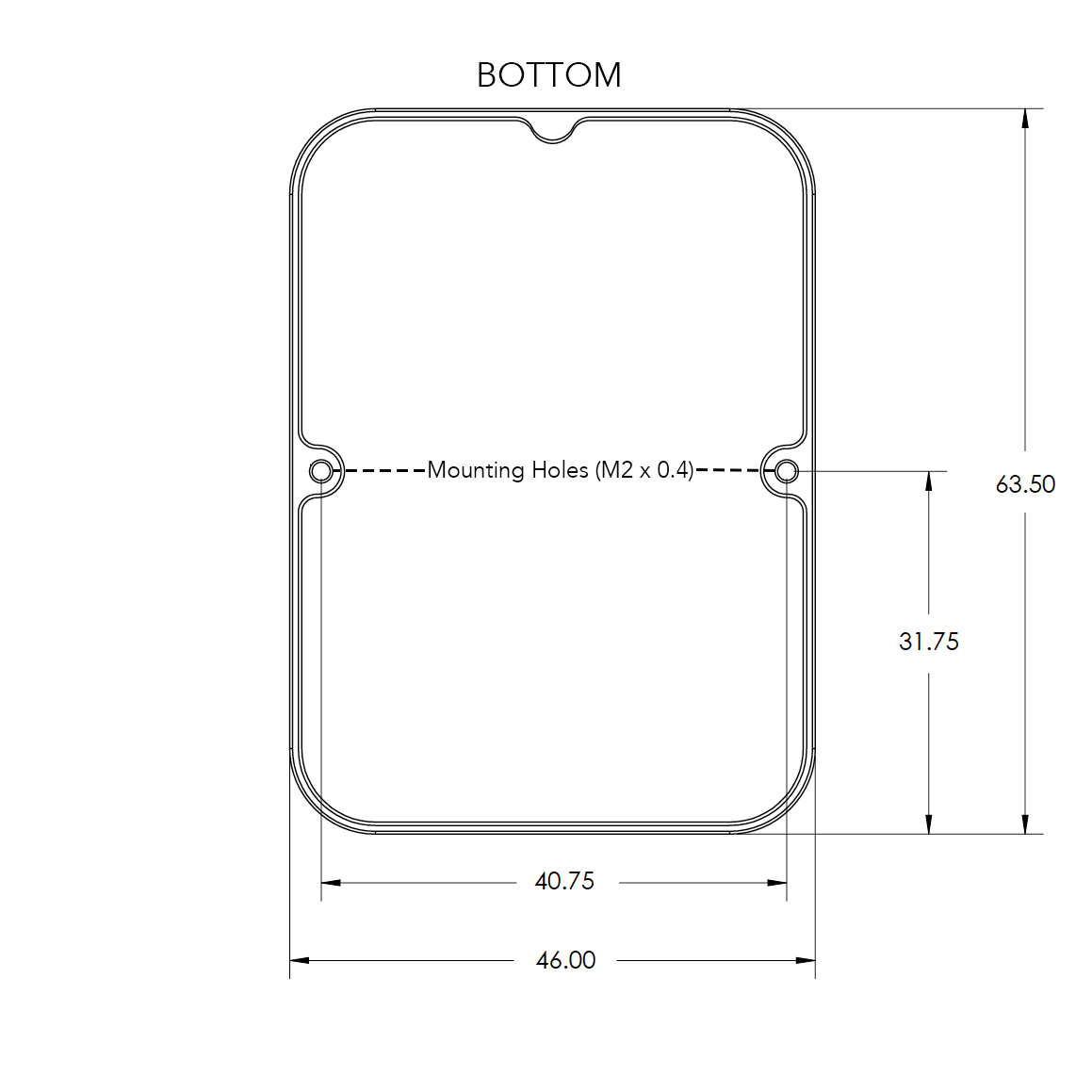
|
Height |
14.03 mm |
|
Width |
46.00 mm |
|
Length |
63.50 mm |
|
Weight |
49 g |
DLS 2 Connectors and Buttons
The sensor kit includes all required interface cables to connect to the DLS 2.
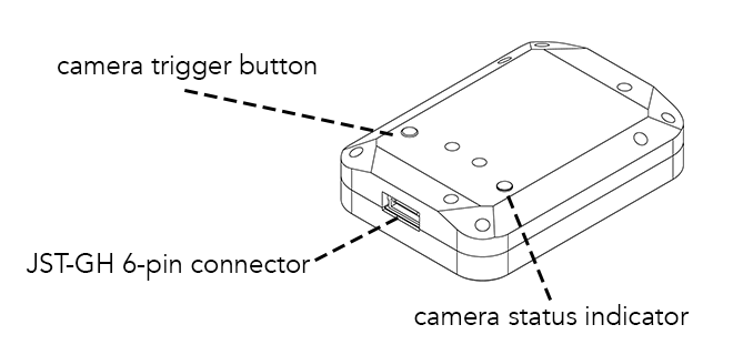
The LED camera status indicator mimics the LED signals on the RedEdge-MX. The signal types are outlined in the User Guide for MicaSense Sensors. The camera trigger button will command a capture on the RedEdge-MX. This is useful for capturing a preflight image of the calibration panel, but care should be taken not to cover or shade any of the light sensors when pressing the button.
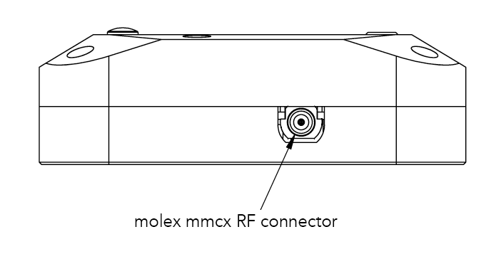
Older DLS 2 have an RF connector. This connector is not used by the DLS 2 or camera.
DLS 2 Installation Guidelines
The DLS 2 should always be the highest object on the aircraft in order to avoid shadows or reflections. It contains an integral GPS sensor that may be utilized for geotagging of the RedEdge-MX imagery if system GPS signals are not provided to the sensor by other means. Install the module where it will have a clear view of the sky, far away from any devices that could interfere with GPS signals (like a data link or video transmitters).
When the DLS 2 starts up, it attempts to calibrate, which requires it to be still and motionless. Ensure that there is no vibration or movement until the DLS 2 has completed this procedure, indicated by normal LED status lights (shown in the User Guide for MicaSense Sensors).
| NOTE |
| The 6-pin connector on the DLS 2 should be facing forward, in the flight direction. Mounting it in the opposite direction will cause the magnetometer calibration process to be backwards, but will otherwise still work. |
Fixed-wing
Always install the DLS 2 at the high-point of the fuselage (if possible) to avoid any shadowing or reflections from the aircraft fuselage, tail, or propellers.
Do not recess or embed the DLS 2 sensor body below the metallic base.
Local reflections could impact light sensor measurements. Avoid bright or metallic paint near the DLS 2 light sensor as this may interfere with incoming light values.
Multirotor
Install the DLS 2 on a rigid post such that it is the highest object on the aircraft.
Ensure that there are no obstructions in the DLS 2’s field of view to the sky, including propellers and other items on the aircraft.
Keep the DLS 2 away from the aircraft GPS. Installing the DLS 2 near the aircraft GPS may impact the aircraft’s GPS reception.
Example Integration
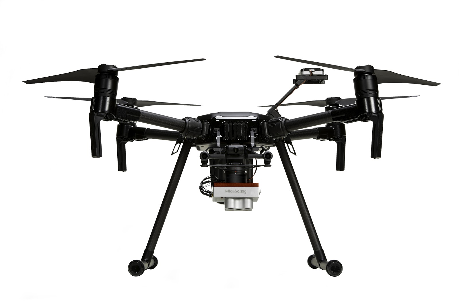
RedEdge-MX and DLS 2 on a Matrice 200. The sensor draws power directly from the Matrice via the Skyport.
The DLS 2 is the highest object on the aircraft.
MicaSense RedEdge-MX and DLS 2 Integration Guide
Revision 04
November 2020
MSPN 900-00022
MicaSense, Inc.
Seattle WA 98103
-
The contents of this guide are subject to change without notice
-
MicaSense, Inc. assumes no liability for incidental or consequential damages arising from the use of this product, and any claims by a third party.
-
Copying of the contents of this guide, in whole or in part is prohibited under the copyright law.
Revision History
| Revision | Description | Date |
| 03 | Previous version | April 2019 |
| 04 | Updated the match Altum guide | November 2020 |
© 2020 MicaSense, Inc